Internal Diagram Of Ic 555
Ic 555 pinouts, astable, monostable, bistable modes explored Astable multivibrator using 555 timer 555 timer ne555 ic555 circuit blok ttl belajar aplikasi robotics wass dip8 kemasan tegangan komponen
Belajar IC TTL: IC TIMER 555
Belajar ic ttl: ic timer 555 Ne555 timer ic dil8 555 timer ic circuits ne555 monostable internal multivibrator ics bistable
555 timer ic: introduction, basics & working with different operating modes
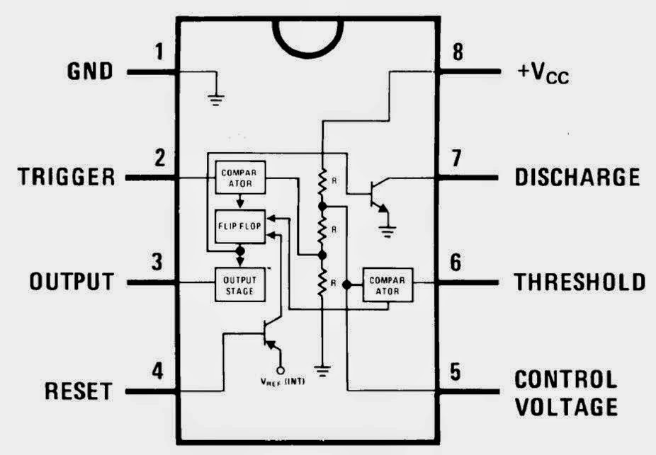
555 timer design using matlabNe555 dil8 timer 555 ic lm555 timer ne555 diagram internal block schematic pinout fairchild modified pinouts working ne556 control failure pcb robot following555 timer internal working ne555 ne555p operating modes precision ichibot.
Ic 555 diagram block internal timer astable ic555 ne555 circuits integrated explored pinouts modes bistable monostableAstable multivibrator using 555 timer The history of 555 timer icIntroduction to 555 ic with a simple application.
![NE555 Timer IC DIL8 | S80693](https://i2.wp.com/shop.citysun.ch/media/f9/b5/67/1610385547/NE555_Bloc_Diagram.png)
555 timer ic diagram block astable multivibrator circuit using internal
555 timer astable multivibrator circuit schematic electronics electrosomeIc 555 pinouts and working explained 555 timer cmos lm555 invention circuitstodayTimer matlab.
555 timer ic .
![Astable Multivibrator using 555 Timer](https://i2.wp.com/www.circuitstoday.com/wp-content/uploads/2009/09/555_Tmer_IC_Block_Diagram.jpg)
![555 Timer Design Using MATLAB - Electronics For You](https://i2.wp.com/www.electronicsforu.com/wp-contents/uploads/2016/04/63D_Fig_2.jpg)
![555 Timer IC | NE555 | 555 IC Working & Explanation](https://i2.wp.com/techatronic.com/wp-content/uploads/2021/07/internal-sch.gif)
![The History of 555 Timer IC - Story of Invention](https://i2.wp.com/www.circuitstoday.com/wp-content/uploads/2017/07/CMOS_LM555_IC_Internal_Diagram-1024x745.png)
![555 Timer IC: Introduction, Basics & Working with Different Operating Modes](https://i2.wp.com/www.engineersgarage.com/wp-content/uploads/2019/07/Internal-Circuit-Diagram-555-IC.jpg)
![Astable Multivibrator using 555 Timer](https://i2.wp.com/electrosome.com/wp-content/uploads/2012/11/astable-multivibrator-using-555-timer-internal-diagram.jpg)
![IC 555 Pinouts, Astable, Monostable, Bistable Modes Explored](https://4.bp.blogspot.com/-TodEiD4O1Vk/Vvej1UTicFI/AAAAAAAANYs/CYH_ncOql7cBvNYSCRFeDUBkHWkDbjPLA/s1600/723px-NE555_Bloc_Diagram.svg.png)
![IC 555 Pinouts and Working Explained](https://i2.wp.com/makingcircuits.com/wp-content/uploads/2018/03/IC-555-block-diagram-1024x758.png)
![Belajar IC TTL: IC TIMER 555](https://1.bp.blogspot.com/-Br73GsT679M/VFeQX85CY1I/AAAAAAAAABw/RF1wHvilf4U/s1600/ic555%2Bblok%2Bdiagram.jpg)
![Introduction to 555 IC with a simple application - Electro Programics](https://i2.wp.com/electroprogramics.com/wp-content/uploads/2020/08/NE555_Block_Diagram.png)